When creating new internal combustion engines, it has long been common practice to use 3D modeling to determine both the current loads and the conditions of air and gas flow in order to optimize designs and their characteristics. A huge number of works are traditionally devoted to these issues [1, 2], but practice shows that not all features of the operation of the presented structures can be taken into account using modeling of normal operating conditions.
This work discusses the features of the air purification (filtration) process in the intake system of a modern internal combustion engine. As is known, increasing environmental requirements have led to the gradual replacement of traditional paper air filters with filters made of so-called “non-woven” synthetic fiber with non-fixed pores (Fig. 1).
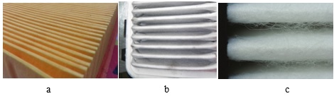
Fig.1. Air filters: a – traditional paper, b – non-woven fiber, c – texture of fibers when magnified
The reasons why manufacturers were forced to switch to a new type of air filter stem from the principles on which the filters work. In fact, paper filters work perfectly according to the mechanism of direct particle retention (the so-called “sieve” effect), i.e. catch and retain all particles that are larger than the pore size or the distance between the fibers in the filter (Fig. 2). Moreover, as the filter becomes dirty, its main characteristics, i.e. cleaning efficiency and screening fineness, increase. However, this also causes serious disadvantages to paper filters, mainly relatively small dirt holding capacity and a rapid increase in hydraulic resistance as they become dirty [3].
It is these shortcomings that have become one of the main reasons for the proliferation of fiber filters. The main difference between fiber and paper filters is that now the particle does not have to get stuck in the fibers for filtration. If the particle simply touches the filter material, this is already enough for effective sedimentation.
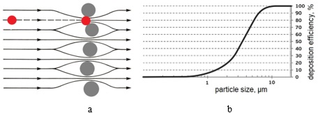
Fig.2. Direct retention of particles by the pores of the material (sieve effect): a - mechanism for retaining particles larger than a given size, b - filtration efficiency depending on the particle size.
As a result, effective filtration occurs at a distance between fibers that significantly exceeds the particle size [4]. Such properties of fiber filters are associated with several processes, including adhesion, diffusion, inertia (Fig. 3) and other related effects.
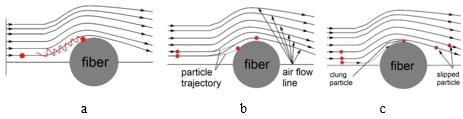
Fig.3. The main effects on which the operation of modern fiber filters is based: a – diffusion, b – inertia, c – engagement.
It is characteristic that noticeable clogging of the fiber filter does not occur over time, since the particles do not clog the pores, but stick to the fibers [5]. In this case, the flow sections between the fibers remain free to one degree or another (Fig. 4). Accordingly, there is no noticeable increase in the hydraulic resistance of the filter during operation, and its influence on engine operation is minimal.
Thus, if old paper filters showed an increase in cleaning efficiency over time with increasing resistance, then modern fiber filters should highlight stable hydraulic resistance with a gradual deterioration in cleaning efficiency as the main feature.
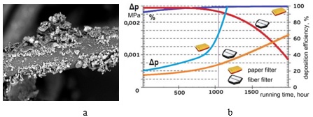
Fig.4. Particles retained on the filter fiber surface (a), and approx comparison by known data of the fiber filter with the paper one in terms of pressure drop and filtration efficiency during operation (b).
On the other hand, experience in investigating the causes of failures [6] shows that many engine designs, as well as their design principles [1], have remained unchanged for many decades, while the mass introduction of fiber filters occurred relatively recently, 10-15 years ago. This means that simply switching from paper filters to fiber ones, with the engine design unchanged can cause new malfunctions that were not previously encountered.
In order to determine such faults, we examined the movement of a dust particle along a curved path (Fig. 5) near the side outlet from the channel in the form of a tee [7], which is often found in the design of air ducts of engines of various types.
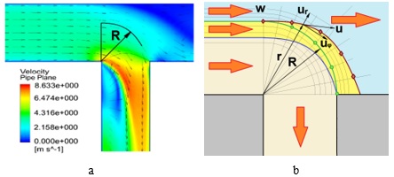
Fig.5. Streamlines during a flow with a side outlet (a) and a calculation scheme for a particle when it moves along a curved path (b).
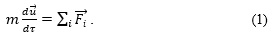
The movement of a particle with mass m, depending on the diameter d and density ρp of the particles (dust consists mainly of quartz, which has a density ρp = 2700 kg/m3), in the air flow obeys Newton’s 2nd law. According to it, the acceleration of a particle is determined by the action of a large number of different forces Fi [8], including gravity, centrifugal, Archimedes (pushing), aerodynamic drag, Coriolis, Basset (related to the history of motion), Saffman (lifting), Magnus (during rotation). In vector form, this is written as [9, 10]:
If we consider the problem in polar coordinates and simplify it, namely, neglect gravity forces to the 1st approximation and set the parameters in the direction perpendicular to the plane of motion of the particle unchanged, then from equation (1) we can obtain a system of 2 equations for the radial and circumferential acceleration of the particle in the form:
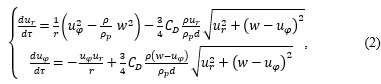
where ur, uφ are the radial and circumferential components of the particle velocity, w is the air flow velocity (for simplicity, it is assumed that the air moves in a circle at a constant velocity), ρ is the air density, CD is the aerodynamic drag coefficient, which is calculated using one of the formulas for spheres (for example, for Reynolds numbers in the range 0.01< Re<700, Klyachko’s formula [4] CD=24⁄Re+4⁄∛Re) is valid).
System (2) is solved numerically with the initial conditions: at =0 φ=0, uφ=w, ur=0 for a given radius R and air flow velocity w for a given particle size. Having accelerations, it is easy to find the components of the particle’s velocity in directions, as well as determine the trajectory of the particle and its deviation from the air flow lines.
For the practical purpose of the study, it is important to obtain the distribution of particles over the channels, i.e. determine how many particles will pass through the side outlet when the flow turns. In the 1st approximation, for small deviations from circular motion, a simple relation was adopted for the particle trajectory (Fig. 5b). It is obtained from the condition: if at the end of the flow turn a particle moves to a radius that is larger than the radius R by an amount ΔR, then we can assume that such a particle would end up at the edge of the channel if it begins a curvilinear movement at the initial radius, which less than R by the same amount ΔR.
Fig. 6 presents the results of calculating the relative number of particles in the direct channel Nex/Nin as the ratio of particles at the outlet Nex to the total number of particles at the inlet Nin at different angles of rotation of the flow in the outlet and at different air velocity (which is proportional to the engine operating mode for a given channel cross-section and volume engine cylinders) for particles of different sizes.
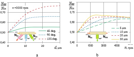
Fig.6. The influence of the side outlet angle (a) and engine operating mode (air velocity in the channel) at different particle sizes (b) on the relative (to the total number of particles at the inlet) dust particle number on the direct outlet.
It is clearly seen that as the angle, particle size and flow velocity increase, the number of particles that “overshoot” the turn increases. This leads to a decrease in the relative number of particles that enter the side outlet, and, accordingly, to an increase in the number of particles in the direct channel to 65-75% of the total number at the inlet. That is, the side exit in the duct redistributes (centrifuges) the particles so that, given the same air flow, more dust will be directed into the straight duct.
Indeed, examples of such dust redistribution have been found in real structures [3, 6]. In Fig. 7 it is clearly visible that the inlet edges of the blades of the turbocharger that received air from the distant channel of the outlet pipe are severely damaged as a result of gas abrasive wear. At the same time, the 2nd compressor where air gets from a side outlet has blades with virtually no wear.
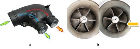
Fig.7. Branch pipe for the flow from the air filter to the turbochargers of the right and left rows of cylinders of a V-8 engine (a) and the inlet edges of the turbocharger blades [4] as a result of operation over 42,000 km of vehicle mileage (b).
Considering that in the case under study, a fiber air filter was used, its combination with a branch pipe, which has an obvious, at first glance, design, actually turned out to be unsuitable for the engine in real operating conditions. With this design, the service life was reduced not only for one of the turbochargers, but also for the entire engine as a whole, since a number of cylinders, which received additional amounts of dust, also had increased wear.
Research results show that not only when developing new designs, but also when making even minor changes to existing designs, process modeling may not be sufficient. It is also necessary to understand well and correctly take into account the operating features; otherwise there is a high risk of reducing reliability and service life.
References
1.Van Basshuysen R., Schäfer F. (Ed.) Internal Combustion Engine. Basics, Components, Systems and Perspectives. Warrendale: SAE International, 2004. 812 p.
2.Chiodi M. An Innovative 3D-CFD Approach towards Virtual Development of Internal Combustion Engines. Wiesbaden: Vieweg+Teubner Verlag / Springer Fachmedien, 2011. 245 p.
3.Khrulev A., Saraev O. Devising a model of the airflow with dust particles in the intake system of a vehicle’s internal combustion engine. Eastern-European Journal of Enterprise Technologies, 2021. 2/1 (110), pp. 61–69. DOI: https://doi.org/10.15587/1729-4061.2021.230113.
4.Khrulev A.E., Saraiev O.V. Local Abrasive Wear in Automobile Internal Combustion Engines. Chisinau: LAP LAMBERT Academic Publishing, 2021. 70 p. ISBN: 978-620-4-72743-1.
5.Trautmann P., M. Durst, A. Pelz, N. Moser. High performance nanofibre coated filter media for engine intake air filtration. AFS 2005 Conference and Expo., 2005. 9 p. Available at: https://www.researchgate.net/publication/292649030 [Accessed 20.10.2023].
6.Khrulev A. Internal combustion engines: Fault expertise and analysis. Monograph in 2 vol. V.2. Practical determination of fault causes. Chisinau: LAP LAMBERT Academic Publishing, 2023. 562 p. ISBN: 978-620-6-15367-2.
7.Sukhapure K., Burns A., Mahmud T., Spooner J. CFD Modelling and Validation of Head Losses in Pipe Bifurcations. Slovenia, 13th International Conference on Heat Transfer, Fluid Mechanics and Thermodynamics, 2017, pp. 489-494.
8.Tang Z., Yu L., Wang F.F., Li N., Chang L., Cui N. Effect of Particle Size and Shape on Separation in a Hydrocyclone. Water, 11 (16), 2019. 19 p. DOI: http://dx.doi.org/10.3390/w11010016.
9.Matoušek V. Flow Mechanism of Sand-Water Mixtures. Delft: Delft University Press, 1997. 258 p.
10.Rudinger G. Fundamentals of Gas Particle Flow. Elsevier, 2012. 156 p.
_______________________________________________________________
Науковий керівник: Сараєв Олексій Вікторович, доктор технічних наук, професор, Міжнародне моторне бюро
|