Traditionally in technical universities resistance of materials studying at the level of the 18th-19th centuries. Students are trained to solve the simplest problems with analytical solutions. The emphasis is placed on various approximate computational methods without due attention to the physical side of the problem to be solved. Then, when graduates of such technical universities come into the workplace, they have to solve complex production tasks to determine the strength and rigidity of structures, and the skills of using modern computing complexes such as ANSYS, NASTRAN, SolidWorks Simulation they lack. For example, much attention in the teaching process has been given to the geometric characteristics of sections, i.e., to those questions that can be solved elementarily by any computing complex. For the competent application of such complexes, the engineer must be able to imagine a priori the operation of the structure, the distribution of stresses in it. For this purpose, it is necessary to develop engineering intuition of students, solving technical problems in tandem with analytical methods and computational methods, such as the finite element method (FEM).
The main idea of student teaching methodology – is the solution of simple structural strength problems by the combined use of resistance of materials and FEM.
The synergy lies in the fact that FEM on the one hand allows students to represent the structure's deflected mode by visualization, while material resistance on the other hand allows to estimate the error in choosing the finite-element mesh and correctly formulate the boundary conditions.
Analytical methods of strength of materials are based on a one-dimensional representation of the structures under investigation. In statically determinate problems, the use of such models is well justified, but in statically indeterminate problems, the error in satisfying the condition of joint deformation may cause a significant error.
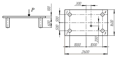
As an example, consider the problem of determining the forces in the four supports of the plate when it is asymmetrically loaded with a concentrated force P, equal to 200 kN (image 1).

Image 1 – calculation scheme
In addition to the three equations of equilibrium (vertical forces and moments with respect to two perpendicular horizontal axes), the condition of joint deformation is used, which in this case is reduced to the requirement to move and the rotation of the plate, as an absolutely rigid body. In other words, all the connection points of the centers of the props with the plate must be in the same plane (coplanarity conditions).
As a result of the analytical solution of the system of equations the following forces in the props have been found: -15 kN; -44 kN; -83 kN; -54 kN.
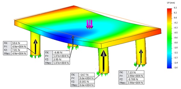
Solve this problem with FEM by using SolidWorks Simulation. As the material of the plate we set low-carbon steel.
As a result of the solution we obtain an diagram of vertical displacements (image 2), from which we can see that the slab bends significantly. This leads to an error in the use of the coplanarity condition, which amounts to 27,5%.
Image 2 – distorted shape of the structure
This combined use of the analytical methods of strength of materials and the finite element method leads to:
1) visualization of the deformed shape of the structure and displacements of its characteristic points;
2) determination of directions and values of support reactions in the lower ends of the props;
3) finding forces in the props.
Thus, through the use of innovative technologies in the teaching of technical mechanics, students develop skills in the joint using of the above calculation techniques with error estimation. In addition, it allows the student to develop engineering intuition.
|


