Tubbing erectors – machines designed to reinforce horizontal mine workings with the help of lining (tubbings or reinforced concrete blocks) – are used in tunneling.
The tubbing erector manipulator (Fig. 1) connects the links of Lever arm 2, Shoulder 3 and Section 4 with the hoisting device using rotational kinematic pairs. The hoisting device is designed for assembling in the tunnel of Pin lining 5. Lever arm 2 link with counter-weight 7 is set on the drive shaft of the hydraulic motor 1 (Support). Two power hydraulic cylinders 6 (Engine) control the links 3 (Shoulder) and 4 (Section).
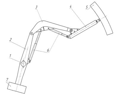
Fig. 1. UT62 tubbing erector manipulator design
By order of JSC Dneprotyazhmash, the scientific school of employees at the National Technical University Dnipro Polytechnic is engaged in the study of dynamic and static parameters for tubbing erectors [1].
For the dynamic analysis of such mechanisms, as a rule, methods of analytical mechanics are used, which, in the general case, make it possible to obtain forces in the drive along a given trajectory of the executive body movement. But in order to calculate the stress-strain state of the mechanism links, it is necessary to perform a resource-intensive dynamic calculation [2].
The task is complicated by the fact that the mechanism links move according to a complex law of motion. Therefore, the authors in the work [3] restrict themselves to studying simplified dynamic models of the UTK-2 erector mechanism.
The UT62 erector main characteristics: tunnel diameter – 9.5 m; lining type – tubbings, blocks; tubbing or block weight is no more than 920 kg.
Based on the JSC Dneprotyazhmash initial documentation, a solid model has been constructed using the SolidWorks Simulation program (Fig. 2).
From the trial calculation of the lever arm with the default finite element mesh, it can be seen that an unacceptably high gradient occurs at the stress concentration points. In addition, the maximum aspect ratio in finite elements reaches 75.6, which is not acceptable in terms of the accuracy criterion. Therefore, the following measures are taken: 15 mm maximum size of the element is set; a mesh management tool is applied (1 mm is the element size, 1.1 is the ratio of the element size in one layer relative to the element size in the previous layer) on the edges, near which the maximum equivalent stresses occur.
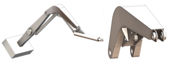
Fig. 2. Tubbing erector manipulator computer model
A simulation case is accepted when the tubbing is placed in the vicinity of a horizontal plane passing through the axis of the tunnel with a diameter of 10.4 m. The tubbing weight (920 kg) and the gripping device weight for this tubbing (630 kg), applied to the axis of the Section link, are considered as the load.
Based on a simplified computational scheme, taking into account the gravity centers of each link and their masses (Fig. 3), an analytical calculation of the torque is performed.
Мtorq = Qload·l1 + Рgrip·l2 + Рs·l3 + Рsh·l4 + Рlev·l5 – Qcbload·l6.
It is designated in Fig. 3: Qload – tubbing weight load; Рgrip – gripping device weight for tubbing; Рsec – section weight; Рsh – shoulder weight; Рlev – lever arm weight; Qcbload – counter-balance load on the lever arm; l1 – maximum shoulder when assembling tubbing; l2 – shoulder of application of the gripping device gravity center; l3 – shoulder of application of the section gravity center; l4 – shoulder of application of the shoulder gravity center; l5 – shoulder of application of the lever arm gravity center; l6 – shoulder of application of the counter-balance gravity center.
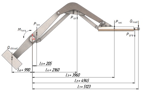
Fig. 3. Tubbing erector manipulator computational scheme
This result is controlled by directly measuring this parameter in the SolidWorks Simulation program, for which a special lever arm on the manipulator shaft is additionally constructed in the computer model (Fig. 2). The calculation in the SolidWorks Simulation program shows the reactive moment value by 10% higher than the value obtained by calculation.
The stress-strain state analysis (Fig. 4) obtained in the calculation shows: 1) the most loaded places where equivalent stresses are in the places of attaching the beckets to the Lever arm link (1080 MPa) and in the places of attaching the edges of the beckets to the Shoulder link (860 MPa); 2) the Section link is the least loaded – 8 MPa; 3) in the entire structure of the manipulator assembly, the stresses, except for the above-mentioned places, do not exceed 50 MPa. In addition, preliminary calculations show that the mechanism mass can reach 6000 kg.
Thus, the following conclusions can be drawn.
The stress-strain state analysis shows that, on the one hand, there are elements in the manipulator whose equivalent stresses are many times higher than the permissible ones. On the other hand, there are parts with low equivalent stresses. Thus, the original design of the tubbing erector manipulator is not of uniform strength.
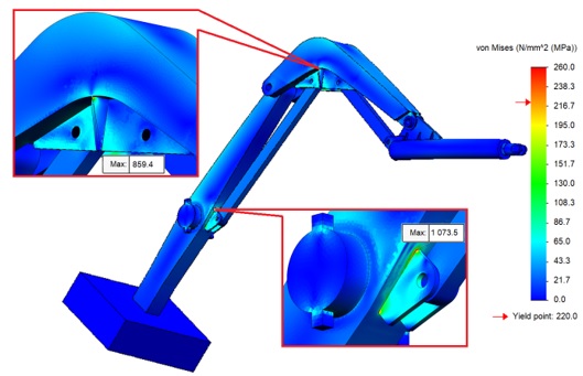
Fig. 4. Tubbing erector manipulator stress-strain state
To ensure the creation of a tubbing erector manipulator design with uniform strength, it is necessary to substantiate the method of computer analysis of the manipulator mechanism stress-strain state in the process of tunneling. In addition, it is necessary to set and solve an optimization problem – to determine the parameters of the tubbing erector manipulator, ensuring the delivery of tubbing to a given position according to the criterion of achieving the minimum mechanism mass and equivalent drive power.
References:
1. Zabolotny K., Sirchenko A., Zhupiev O. The development of idea of tunnel unit design with the use of morphological analysis. New Developments in Mining Engineering 2015. Teoretical and Practical Solutions of Mineral Resources Mining. – CRC Press/Balkema, 2015 – P. 205 – 211
2. Zabolotnyi, K., Zhupiiev, O., Panchenko, O. Substantiation of parameters for the tunnel erector with two manipulators. Advanced Engineering Forum – Switzerland: Trans Tech Publications, 2017. – Vols. 25, 43-53.
3. Zabolotnyi, K., Zhupiiev, O., Panchenko, O. & Tipikin A. Development of the concept of recurrent metamodeling to create projects of promising designs of mining machines. Ukrainian School of Mining Engineering – 2020: Materials E3S Web of Conferences. 23 October 2020. Vols. 201 (01019), 55–70. DOI: 10.1051/e3sconf/202020101019.
|